Understanding the Op-Amp 741 Schematic: A Detailed Guide
The op-amp 741 is a classic integrated circuit that has been widely used in various electronic applications. Its schematic, which is the blueprint of its internal circuitry, is a fascinating subject to explore. In this article, we will delve into the intricacies of the op-amp 741 schematic, providing you with a comprehensive understanding of its design and functionality.
Basic Structure of the Op-Amp 741
The op-amp 741 is a high-gain, differential amplifier with a closed-loop gain of approximately 100,000. It consists of several stages, including the input stage, the voltage amplifier stage, and the output stage. The input stage is responsible for providing a high input impedance and a low output impedance, while the voltage amplifier stage amplifies the differential input signal. The output stage drives the load with high current capability.

| Stage | Description |
|---|---|
| Input Stage | High input impedance, low output impedance, and differential input signal |
| Voltage Amplifier Stage | Amplifies the differential input signal |
| Output Stage | Drives the load with high current capability |
The op-amp 741 schematic features a differential input pair, which consists of two transistors (Q1 and Q2) that are biased in a common-emitter configuration. This configuration provides a high input impedance and a low output impedance, which are essential for the op-amp’s operation.
Internal Circuitry of the Op-Amp 741
The internal circuitry of the op-amp 741 is quite complex, with numerous transistors, resistors, and capacitors. The following is a brief overview of its key components:
- Transistors: The op-amp 741 contains a total of 11 transistors, including the differential input pair, the voltage amplifier stage, and the output stage.
- Resistors: There are 15 resistors in the op-amp 741, which are used for biasing, feedback, and other functions.
- Capacitors: The op-amp 741 has three capacitors, which are used for filtering and stabilizing the circuit.
The differential input pair (Q1 and Q2) is biased using a voltage divider network, which ensures that the transistors operate in the active region. The voltage amplifier stage is a long-tailed pair configuration, which provides a high gain and a low output impedance. The output stage is a push-pull configuration, which allows the op-amp to drive loads with high current capability.
Pin Configuration of the Op-Amp 741
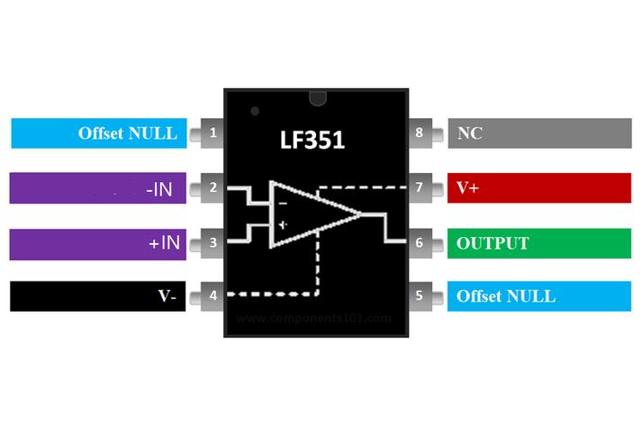
The op-amp 741 is a 8-pin DIP (Dual In-line Package) integrated circuit. The pin configuration is as follows:

- Pin 1: Negative input (鈥揑N)
- Pin 2: Positive input (+IN)
- Pin 3: Output (OUT)
- Pin 4: Negative supply voltage (鈥揤S)
- Pin 5: No connection (NC)
- Pin 6: Positive supply voltage (+VS)
- Pin 7: No connection (NC)
- Pin 8: No connection (NC)
It is important to note that pins 5, 7, and 8 are not connected to any internal circuitry and can be left unconnected. The negative supply voltage (鈥揤S) and the positive supply voltage (+VS) are used to power the op-amp and provide the necessary voltage levels for its operation.
Applications of the Op-Amp 741
The op-amp 741 is a versatile integrated circuit that can be used in a wide range of applications. Some of the most common applications include:


