Understanding the Non-Inverting Op Amp Configuration
When it comes to operational amplifiers (op-amps), the non-inverting configuration is one of the most widely used and versatile setups. By understanding how it works and its various applications, you can harness the full potential of this powerful electronic component. In this article, we will delve into the intricacies of the non-inverting op amp configuration, exploring its principles, circuit design, and practical applications.
Basic Principles of the Non-Inverting Op Amp Configuration
The non-inverting op amp configuration is characterized by its ability to amplify an input signal without inverting its phase. This is achieved by connecting the input signal to the non-inverting input terminal of the op-amp, while the output is taken from the output terminal. The inverting input terminal is typically grounded, which is where the name “non-inverting” comes from.

One of the key advantages of the non-inverting configuration is its high input impedance, which means it draws very little current from the input signal source. This makes it ideal for use with high-impedance sources, such as transistors or other op-amps.
Circuit Design of the Non-Inverting Op Amp Configuration
Designing a non-inverting op amp circuit involves selecting the appropriate components and configuring them in a way that meets your specific requirements. Here are the main components you will need:
- Op-Amp: Choose an op-amp with the desired specifications, such as bandwidth, input offset voltage, and power supply voltage range.
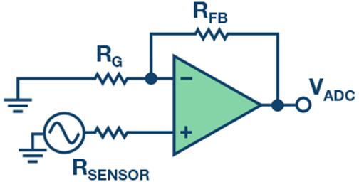
- Input Resistor (R1): This resistor sets the gain of the circuit. The gain is determined by the formula: Gain = 1 + (Rf / R1), where Rf is the feedback resistor connected between the output and the inverting input terminal.
- Feedback Resistor (Rf): This resistor, along with R1, determines the gain of the circuit. As mentioned earlier, the gain is calculated using the formula: Gain = 1 + (Rf / R1).
Here is a basic non-inverting op amp circuit diagram:
| Component | Description |
|---|---|
| Op-Amp | Operational Amplifier |
| R1 | Input Resistor |
| Rf | Feedback Resistor |
By adjusting the values of R1 and Rf, you can achieve different gain levels for your circuit. For example, if you want a gain of 10, you can use R1 = 1k惟 and Rf = 9k惟.

Practical Applications of the Non-Inverting Op Amp Configuration
The non-inverting op amp configuration has a wide range of practical applications in various electronic systems. Here are some of the most common ones:
- Signal Amplification: The non-inverting configuration is often used to amplify low-level signals, such as those from sensors or transducers.
- Buffering: By using a non-inverting op amp as a buffer, you can isolate the input signal from the output, preventing any loading effects on the source.
- Signal Conditioning: The non-inverting configuration can be used to condition signals, such as filtering, rectifying, or converting them to different voltage levels.
- Voltage Follower: By setting the gain to 1, you can create a voltage follower circuit, which provides a high-impedance output that follows the input voltage.
Here is an example of a non-inverting op amp circuit used as a voltage follower:
| Component | Description |
|---|---|
| Op-Amp | Operational Amplifier |
| R1 | Input Resistor (1k惟) |
Rf
Related Stories |


