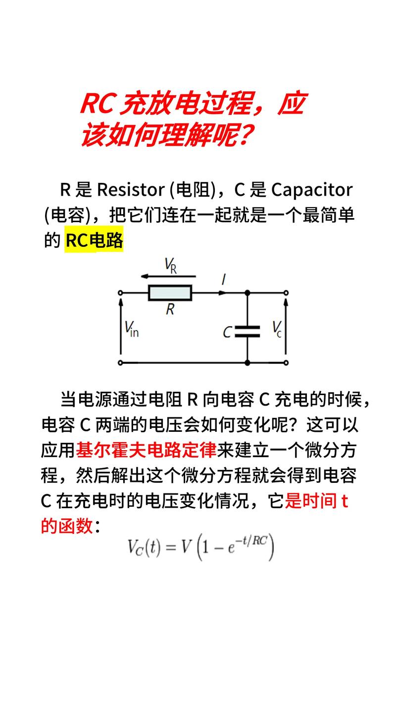
Understanding the Input Resistance of an Op Amp
When delving into the world of operational amplifiers (op-amps), one crucial parameter that often comes under scrutiny is the input resistance. This value plays a pivotal role in determining the performance and suitability of an op-amp for various applications. In this article, we will explore the concept of input resistance in detail, examining its significance, calculation methods, and practical implications.
What is Input Resistance?
Input resistance, often denoted as Rin, refers to the resistance that an op-amp presents to the signal source connected to its input terminals. It is a measure of how much the op-amp draws current from the input signal source. A higher input resistance implies that the op-amp draws less current, which is desirable in many applications to minimize loading effects on the signal source.

Significance of Input Resistance
The input resistance of an op-amp is crucial for several reasons:
-
Minimizing Loading Effects: As mentioned earlier, a high input resistance ensures that the op-amp draws minimal current from the input signal source, thereby minimizing loading effects and preserving the integrity of the signal.
-
Improving Accuracy: In precision applications, such as data acquisition systems or signal processing, the input resistance can significantly impact the accuracy of the measurements. A high input resistance reduces the error introduced by the op-amp’s input bias current.
-
Enhancing Impedance Matching: In some applications, such as RF amplifiers, impedance matching is essential to maximize power transfer. The input resistance of the op-amp plays a crucial role in achieving this goal.

Calculating Input Resistance
Calculating the input resistance of an op-amp can be done using the following formula:

In this formula, Rin represents the input resistance, Iin is the input bias current, and Vout is the output voltage. It is important to note that the input resistance is typically specified in the op-amp’s datasheet and may vary with temperature and supply voltage.
Input Resistance in Different Op-Amp Configurations
The input resistance of an op-amp can vary depending on the configuration in which it is used. Here are some common configurations and their corresponding input resistances:
| Configuration | Input Resistance (Rin) |
|---|---|
| Non-Inverting Amplifier | High (typically equal to the feedback resistor, Rf) |
| Inverting Amplifier | High (typically equal to the feedback resistor, Rf) |
| Non-Inverting Summing Amplifier | High (typically equal to the feedback resistor, Rf) |
| Inverting Summing Amplifier | High (typically equal to the feedback resistor, Rf) |
| Buffer Amplifier | High (typically equal to the feedback resistor, Rf) |
As you can see, the input resistance in these configurations is typically high, which is beneficial for minimizing loading effects and improving accuracy.
Practical Implications of Input Resistance
Understanding the input resistance of an op-amp is essential for designing circuits that meet specific requirements. Here are some practical implications:
-
Choosing the Right Op-Amp: When selecting an op-amp for a particular application, it is crucial to consider its input resistance. For example, if you are designing a low-noise amplifier, you would want to choose an op-amp with a high input resistance to minimize noise introduced by the input bias current.
-
Designing Impedance-Matched Circuits: In applications where impedance matching is critical, such as RF amplifiers, the input resistance of the op-amp must be taken into account to ensure optimal performance.
-
Optimizing Circuit Performance: By understanding the input resistance of an op-amp, you can design circuits that minimize loading effects


