Understanding the Op Amp as Comparator Circuit
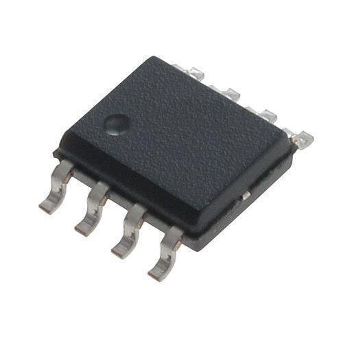
When it comes to electronic circuits, the operational amplifier (op amp) is a versatile component that can be used in various configurations. One such configuration is the op amp as a comparator. In this article, we will delve into the intricacies of this circuit, exploring its working principle, applications, and design considerations.
How Does an Op Amp as Comparator Work?
An op amp as a comparator circuit is designed to compare two voltages and produce a digital output based on the comparison result. The basic principle is straightforward: if the voltage at the non-inverting input (+) is greater than the voltage at the inverting input (-), the output will be high; otherwise, it will be low. This makes the op amp an excellent choice for implementing a comparator function.

Here’s a simple circuit diagram of an op amp as a comparator:
| Component | Description |
|---|---|
| Op Amp | The operational amplifier is the core component of the circuit, responsible for comparing the voltages at the input terminals. |
| Reference Voltage (Vref) | The reference voltage is the voltage level against which the input voltage is compared. |
| Input Voltage (Vin) | The input voltage is the voltage level to be compared with the reference voltage. |
| Output | The output is a digital signal that indicates whether the input voltage is greater than or less than the reference voltage. |
In this circuit, the non-inverting input (+) is connected to the reference voltage (Vref), while the inverting input (-) is connected to the input voltage (Vin). The op amp amplifies the difference between the two input voltages and drives the output accordingly.
Applications of Op Amp as Comparator Circuit
The op amp as a comparator circuit finds applications in various fields, including:
-
Signal detection: The circuit can be used to detect the presence or absence of a specific voltage level in a signal.

-
Threshold detection: It can be used to trigger an action when the input voltage crosses a certain threshold.
-
Amplitude measurement: The circuit can be used to measure the amplitude of an analog signal.
-
Frequency measurement: It can be used to measure the frequency of a signal by comparing the input voltage with a reference voltage.
Design Considerations for Op Amp as Comparator Circuit
When designing an op amp as a comparator circuit, several factors need to be considered:
-
Input offset voltage: The input offset voltage is the voltage difference between the two input terminals when the output is at zero. A lower input offset voltage is desirable for better accuracy.
-
Input bias current: The input bias current is the current flowing into the input terminals of the op amp. A lower input bias current is preferable to minimize the loading effect on the input signal.
-
Output voltage swing: The output voltage swing is the range of output voltage levels the op amp can produce. A wider output voltage swing is desirable for driving loads with varying requirements.
-
Power supply rejection ratio (PSRR): The PSRR is the ability of the op amp to reject noise and variations in the power supply voltage. A higher PSRR is preferable for better performance in noisy environments.
Choosing the right op amp for the application is crucial. Some popular op amps suitable for comparator circuits include the LM393, LM741, and TL081.
Conclusion
In conclusion, the op amp as a comparator circuit is a powerful tool for comparing voltages and generating digital outputs. By understanding its working principle, applications, and design considerations, you can create effective and reliable comparator circuits for various applications.


