Understanding the Op Amp Inverting Amplifier Circuit
When it comes to electronic amplifiers, the Op Amp inverting amplifier circuit stands out as a fundamental and versatile design. By utilizing an operational amplifier (op amp) in an inverting configuration, this circuit offers a wide range of applications, from signal conditioning to signal processing. In this article, we will delve into the intricacies of the op amp inverting amplifier circuit, exploring its working principle, design considerations, and practical applications.
How Does the Op Amp Inverting Amplifier Circuit Work?
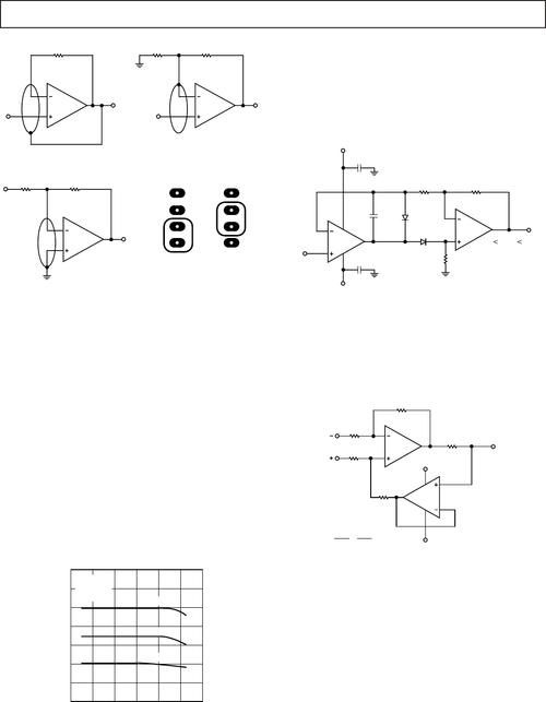
The op amp inverting amplifier circuit operates based on the principle of negative feedback. In this configuration, the input signal is applied to the inverting input terminal of the op amp, while the output signal is taken from the output terminal. The non-inverting input terminal is connected to a voltage reference, typically ground. The key components of this circuit include the op amp, resistors, and capacitors.

When the input signal is applied to the inverting input terminal, it creates a voltage difference between the inverting and non-inverting input terminals. This voltage difference is amplified by the op amp, and the output signal is inverted in phase. The gain of the circuit is determined by the ratio of the feedback resistor (Rf) to the input resistor (Rin). The formula for the gain is given by:
| Gain (A) | = | (Rf / Rin) |
|---|
By adjusting the values of Rf and Rin, you can achieve the desired gain for your application. Additionally, the op amp inverting amplifier circuit can be used to provide additional functionalities, such as voltage offset, filtering, and buffering.
Design Considerations for the Op Amp Inverting Amplifier Circuit
When designing an op amp inverting amplifier circuit, there are several factors to consider to ensure optimal performance:
-
Op Amp Selection: Choose an op amp with high input impedance, low output impedance, and sufficient bandwidth for your application. Additionally, consider the power supply requirements and the common-mode input voltage range.

-
Resistor Values: Select appropriate resistor values for Rf and Rin to achieve the desired gain. Ensure that the resistors have low tolerance and high power ratings to minimize errors and heat dissipation.
-
Power Supply: Provide a stable and appropriate power supply voltage for the op amp. The power supply voltage should be within the specified range of the op amp and should be capable of delivering sufficient current.
-
Input and Output Impedance: Consider the input and output impedance requirements of your application. The op amp inverting amplifier circuit can be designed to have high input impedance and low output impedance, making it suitable for various signal sources and loads.
-
Temperature Range: Ensure that the op amp inverting amplifier circuit operates within the specified temperature range to maintain its performance and reliability.
Practical Applications of the Op Amp Inverting Amplifier Circuit
The op amp inverting amplifier circuit finds applications in various fields, including:
-
Signal Conditioning: The circuit can be used to amplify and filter signals, making them suitable for further processing or analysis.
-
Signal Processing: The circuit can be employed in signal processing applications, such as audio amplification, data acquisition, and sensor interfacing.
-
Instrumentation: The op amp inverting amplifier circuit is widely used in instrumentation systems for measuring and monitoring various physical quantities.
-
Control Systems: The circuit can be utilized in control systems for amplifying and processing feedback signals, ensuring accurate and stable control.
In conclusion, the op amp inverting amplifier circuit is a fundamental and versatile design that offers numerous advantages in various applications. By understanding its working principle, design considerations, and practical applications, you can effectively utilize this circuit to meet your specific requirements.


