Op Amp 741 Pinout: A Comprehensive Guide
The LM741 operational amplifier, often simply referred to as the 741, is one of the most popular and widely used operational amplifiers in the world. Its versatility and reliability have made it a staple in various electronic circuits. In this article, we will delve into the pinout of the 741 op amp, exploring its various pins and their functions in detail.
Pin Configuration
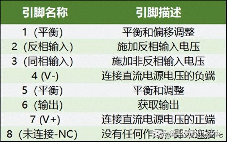
The LM741 op amp has eight pins, which are arranged in a standard dual-in-line package (DIP). The pin configuration is as follows:

| Pin Number | Function |
|---|---|
| 1 | Input Offset Null |
| 2 | Non-Inverting Input |
| 3 | Output |
| 4 | Ground |
| 5 | Inverting Input |
| 6 | Power Supply (Positive) |
| 7 | Power Supply (Negative) |
| 8 | No Connection (NC) |
Now, let’s take a closer look at each pin and its function.
Pin 1: Input Offset Null
Pin 1 is used to adjust the input offset voltage of the op amp. The input offset voltage is the voltage difference between the two input terminals when the output is at zero. By connecting a potentiometer between pins 1 and 8, you can nullify the input offset voltage, ensuring that the output is as close to zero as possible when the inputs are equal.
Pin 2: Non-Inverting Input
Pin 2 is the non-inverting input of the op amp. When a signal is applied to this pin, the output will be in phase with the input. This pin is often used in voltage follower circuits, where the op amp amplifies the input signal without inverting its phase.
Pin 3: Output
Pin 3 is the output of the op amp. It provides the amplified version of the input signal. The output can be either positive or negative, depending on the configuration of the circuit.

Pin 4: Ground
Pin 4 is the ground pin of the op amp. It provides a reference point for the circuit and is connected to the negative terminal of the power supply.
Pin 5: Inverting Input
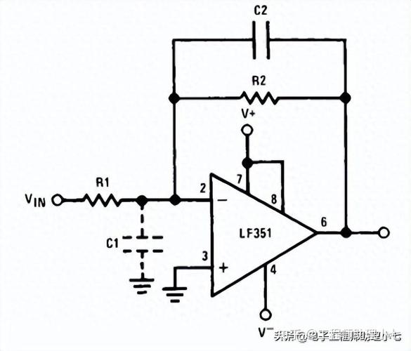
Pin 5 is the inverting input of the op amp. When a signal is applied to this pin, the output will be inverted with respect to the input. This pin is often used in inverting amplifiers, where the gain of the circuit can be controlled by adjusting the feedback resistor.
Pin 6: Power Supply (Positive)
Pin 6 is the positive power supply pin of the op amp. It provides the necessary voltage for the op amp to operate. The voltage level should be within the specified range for the particular op amp model.
Pin 7: Power Supply (Negative)
Pin 7 is the negative power supply pin of the op amp. It provides the necessary voltage for the op amp to operate. The voltage level should be within the specified range for the particular op amp model.
Pin 8: No Connection (NC)
Pin 8 is not connected to any internal circuitry and can be left unconnected. It is often used as a placeholder for additional pins in other op amp packages.
In conclusion, the LM741 op amp pinout is a crucial aspect of understanding its operation and applications. By familiarizing yourself with the functions of each pin, you can design and implement various circuits using this versatile op amp.


